Obtained the MiniTec Profile and Connector Files
We were tasked with drafting up and drawing various details relating to the connections for the Bus Stop structure. A major new addition to the project were the MiniTec profile systems: extruded metal beams that provided great strength and flexibility with its usage. Various proprietary MiniTec connectors could be used in combination with these extruded beams to form joints, supports and dynamic connections.
The detail drawings we were tasked with had many of these frame profiles displayed in section, and rather than physically drawing them from scratch, I obtained relevant MiniTec files from the website (which can be found here )
Two other files were additionally obtained for 3D printing purposes as per our clients wishes. The goal with these connection pieces were to provide a physical 3D printed 1:1 prototype for display to the engineers.
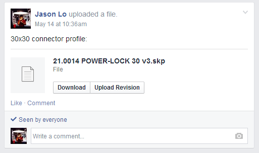
The four files that were obtained were:
The MiniTec website provides all their products available for digital download in the form of CAD files. Unfortunately, the downloadable options available were 3D STEP, Solidworks or Autodesk Inventor, of which none of the group members would have been able to open. As a result, I downloaded Solidworks and all the necessary files off the MiniTec website in order to convert them to a common format that everyone in the project could utilise. I converted the files to either .3ds (3DS Max), .skp (Sketchup) or if necessary .dwg (AutoCAD).
The conversion process itself involved:
1. Open file up in Solidworks
2. Export the file as a .3ds format
3. Open the .3ds file in 3DS Max
4. or Open the .3ds file in Sketchup and save as .skp
5. or Open the .3ds file in Sketchup and export as .dwg
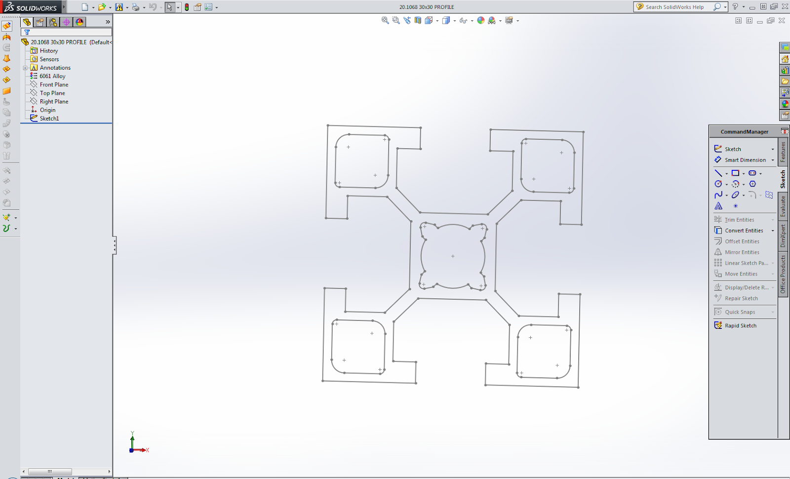
Evidence:
MiniTec files opened up in Solidworks


MiniTec Files converted to 3DS Max, Sketchup and AutoCAD


----------------------------------------------------------------------------------------------------------------------------------
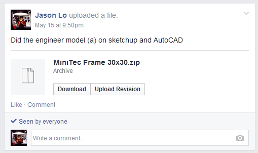
MiniTec Engineering Frame
A frame was proposed to be made purely with MiniTec components in order to house both LCD screens at either ends of the Bus Stop structure. The frame was to be in the detail drawings later on so I created a model and drafted drawings based around the original sketches drafted up by the engineers.
Evidence:
Evidence:
Original supplied drawing

Sketchup Model & AutoCAD Drawing


File for download (2 AutoCAD files, 1 Sketchup file, 1 PDF file):
----------------------------------------------------------------------------------------------------------------------------------
Weekly Meetings with Eliot
Weekly meetings and email communications with Eliot were continued through till the end of the project. The purpose of these meetings were to update Elliot with our progress and obtain any updates from his side of the project. These meetings proved valuable as I was able to relay information to the group involving the completion of a brand new bus stop design (made completely by Elliot via Grasshopper), as well as the obtaining of a 3D printed model he had made to show to the group in addition to the actual file so the group could progress further with the project.
Evidence:
Consult/refer to Elliot regarding my weekly appearances and conversations
Obtaining the new updated design by Elliot (Emails)


Converting the file from .3ds to .skp for the group to use


File Download (1 dxf AutoCAD file, 1 Sketchup file, 1 3DS max file)
----------------------------------------------------------------------------------------------------------------------------------
Group Organisation
Throughout the remainder of the project, I relayed information from the Client to the group, as well as organised member roles and provided reminders and updates for the group.
Evidence:


Evidence:
----------------------------------------------------------------------------------------------------------------------------------
3D Printed Components for Group
In addition to being tasked with creating detail drawings of the connections, we were also responsible for transforming these details into 1:1 prototypes. The objective of this is to provide a deeper understanding of the relevant detail joint and identify any glaring errors or alterations that should be made.
Approximately half the group required 3D printed components in their details, so I took the initiative and utilised the 3D printers to create the components they needed.
In order for this to occur, I had to be trained/had to learn how to utilise both MakerWare and how to operate the MakerBot Replicator 2. I also created all the model files that were printed in this group and did the conversion process to the required .STL file.
Evidence:
Modelling the 3D components needed:


Setting up the components on MakerWare


3D Printer malfunction

PLA that got jammed in the printer head


Approximately half the group required 3D printed components in their details, so I took the initiative and utilised the 3D printers to create the components they needed.
In order for this to occur, I had to be trained/had to learn how to utilise both MakerWare and how to operate the MakerBot Replicator 2. I also created all the model files that were printed in this group and did the conversion process to the required .STL file.
Evidence:
Modelling the 3D components needed:
Setting up the components on MakerWare
3D Printing the pieces (1st run resulted in an unfortunate jam in the printer head and had to be fixed and reprinted)
3D Printer malfunction
Final successful run of prints
File downloads
30x30 Profile STL
Video Evidence
----------------------------------------------------------------------------------------------------------------------------------
Detail Drafting
Evidence:
Original Detail 6 and 6B sketches by Hank
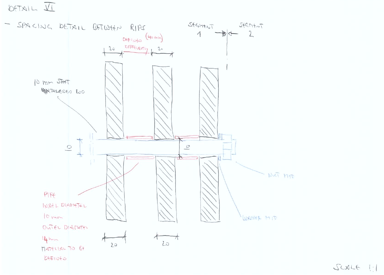

Revised and drafted up in AutoCAD


File Download (2 AutoCAD .dwg files)
----------------------------------------------------------------------------------------------------------------------------------
Fabrication of Detail Prototype (Detail 6 + 6A + 6B)
I created a 1:1 scale prototype detail model to represent detail's 6, 6A and 6B.
This involved purchasing and sourcing all the materials, designing the laser cutting sheets with Illustrator, laser cutting the pieces and then finally assembling the model itself.
Evidence:


This involved purchasing and sourcing all the materials, designing the laser cutting sheets with Illustrator, laser cutting the pieces and then finally assembling the model itself.
Evidence:
Cutting the giant sheets from bunnings into useable laser cut sizes (300x600mm)
Creating the laser cut files on Illustrator
Gluing Cut Pieces Together
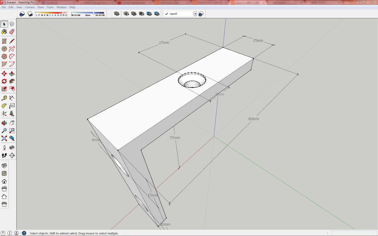
Fabricated the L bracket to fit the model and modelled a countersunk hole to fit countersunk screws
Creating the spacers by cutting pipe down to specific lengths
Assembling the model together
A laser cut sheet and model had been designed before hand and was based around a 1:5 scale model of 1/8th of the full bus stop size. This model was to represent and display where certain details in the model were located. The base for the model to sit upon was completed however, the rest of the model was left incomplete as details of the design had changed at the last minute rendering my 1:5 model useless.
Evidence
Sketchup model of the 1:5 incorporating all the details so far
The laser cut sheet for the obsolete model (4 out of the 12)
The Laser Cut platform
----------------------------------------------------------------------------------------------------------------------------------
Contribution to Group Wiki Page
A group wiki was created as required by the course outline for the course. The group wiki also provides invaluable information for both the client and the ARUP engineers who will be overseeing the calculations of the structure's loading forces.
Within the group wiki, I have created and supplied the written and graphical content for the following pages as well as provided a large number of files available for the public and clients to download:
Project Brief
Initial Concept
Australian Standards and Bus Stop Guidelines
Structural Materials
3D Printing Files
3D Printing
I have also supplied content in conjunction with others on the following pages:
Project Overview
Interim Concept
Laser Cutting
Laser Cut Models
3D Model Files
Laser Cutting Files
Evidence:
Website link - Bus Stop of the Future
Wiki contribution log


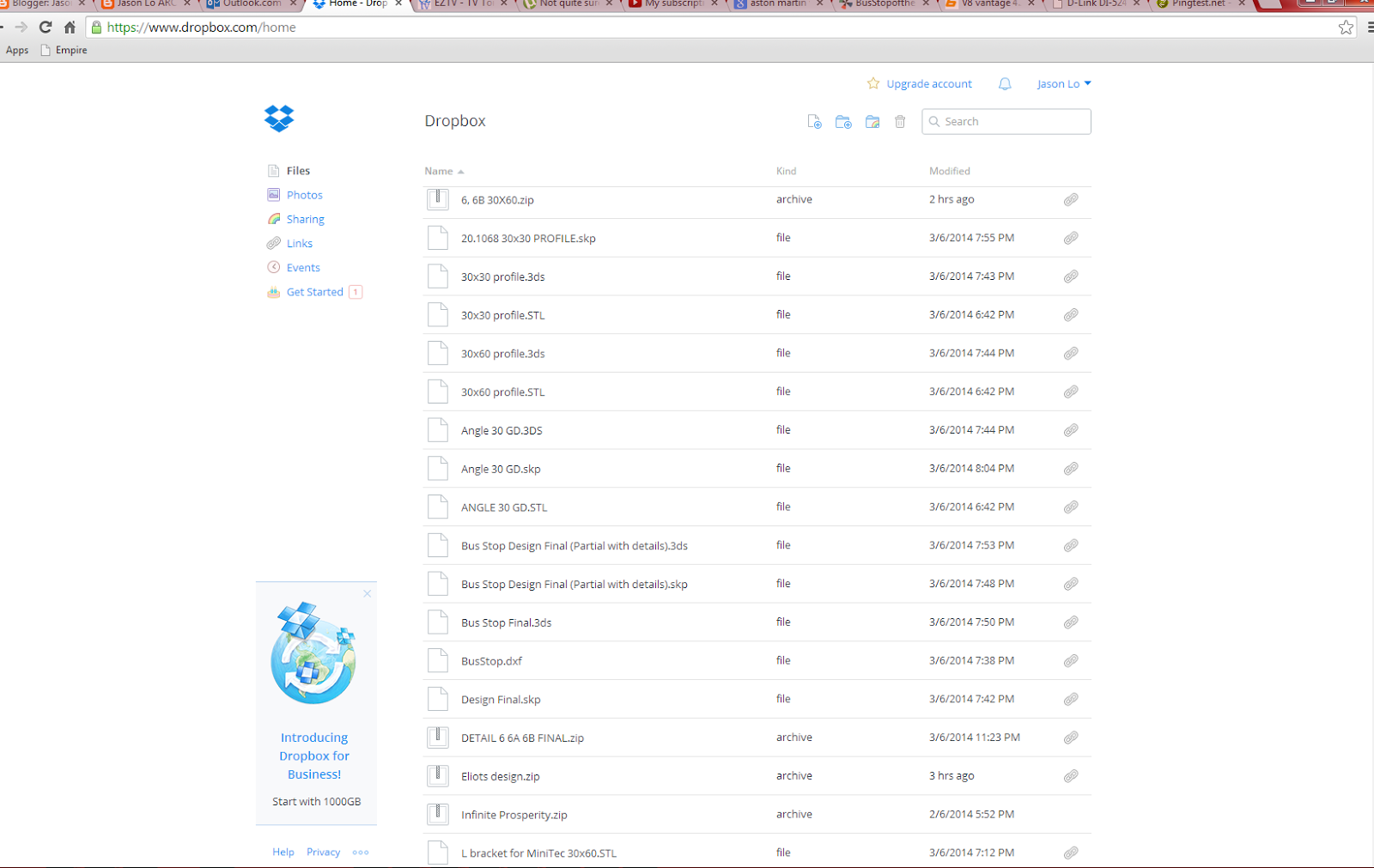
Drop box account with the linked files for the public and clients to download
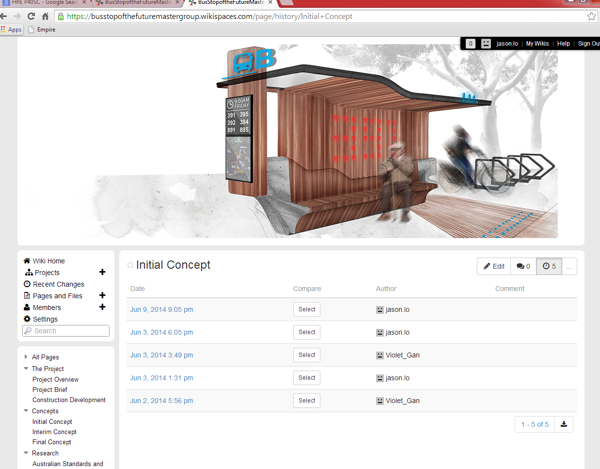
Example of graphical content supplied (photo-shopped Eliot's model to be more presentable for public viewing)
Before and after's


----------------------------------------------------------------------------------------------------------------------------------
Final Summary of Work
Summary list of the individual work I have done
1. Downloaded, converted and supplied every MiniTec profile file/model which was used by the group for their details and their models
2. Created and modelled the MiniTec engineering frame
3. Weekly meetings and communications with Eliot
4. Obtained and converted the final design model in dxf and 3ds format for the group to use
5. Relayed information from the Client to the group, as well as organised member roles, reminders and updates
6. Modelled and converted the MiniTec files from the website into .STL formats
7. 3D printed all the components used in the groups models through MakerWare and the MakerBots in the FBE lab
8. Drafted both details 6 and 6B in AutoCAD
9. Fabricated the 1:1 model for details 6, 6A and 6B (purchased/sourced materials, created laser cutting files, laser cut the pieces and glued/assembled all the components together)
10. Designed and partially laser cut a 1:5 model representing locations of various details
11. Contributed heavily to the group wiki website (sole creation of 6 pages and contribution to 6 more)